Sometimes, to start the engine, you need to pre-fill the power supply system with fuel - this task is solved using a manual booster pump. Read about what a manual fuel pump is, why it is needed, what types it is and how it works, as well as the selection and replacement of these components, read the article.
What is a manual fuel pump?
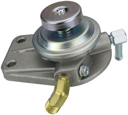
Manual fuel pumping pump (manual fuel pump, fuel pump) is an element of the fuel system (power system) of internal combustion engines, a low-capacity pump with a manual drive for pumping the system.
The manual fuel pump is used to fill the lines and components of the fuel system before starting the engine after a long period of inactivity, after replacing fuel filters or performing other repairs during which fuel residues were drained. Usually, equipment with diesel engines is equipped with such pumps, they are much less common on gasoline engines (and, mainly, on carburetor engines).
Types of fuel booster pumps
Manual fuel pumps are divided into several groups according to the principle of operation, the type and design of the drive, and the method of installation.
According to the principle of operation, manual transfer pumps are of three main types:
• Membrane (diaphragm) - can have one or two membranes;
• Bellows;
• Piston.
Pumps can be equipped with two types of drive:
• Manual;
• Combined - electric or mechanical from the engine and manual.
Only manual drives have bellows pumps and the bulk of manual diaphragm pumps. Piston pumps most often have a combined drive, or combine two separate pumps in one housing - with a mechanical and manual drive. In general, units with a combined drive are not manual pumps - they are fuel (in gasoline engines) or fuel priming (in diesel engines) pumps with the ability to perform manual pumping.
According to the design of the drive, diaphragm and piston pumps are:
• With lever drive;
• With push-button drive.

Diaphragm fuel pump with combined drive
In pumps of the first type, a swinging lever is used, in units of the second type - a handle in the form of a button with a return spring. In bellows pumps, there is no drive as such, this function is performed by the body of the device itself.
Finally, manual pumps can have different installations:
• In the rupture of the fuel line;
• Directly on the fuel filter;
• In various places near the elements of the fuel system (near the fuel tank, next to the engine).
Light and compact bellows pumps ("pears") are introduced into the fuel line, they do not have a rigid installation on the engine, body or other parts. Diaphragm pumps with a push-button drive ("frogs"), made in the form of a compact unit, are mounted on fuel filters. Piston and diaphragm pumps with lever and combined drive can be mounted on the engine, body parts, etc.
Design and principle of operation of fuel hand pumps
The distribution of diaphragm and bellows pumps is due to the simplicity of their design, low cost and reliability. The main disadvantage of these units is relatively low performance, but in most cases it is more than enough to pump the fuel system and successfully start the engine.

Manual fuel pumps of bellows type ("pears")
Bellows pumps are the most simply arranged. They are based on an elastic body in the form of a rubber bulb or a corrugated plastic cylinder, at both ends of which there are valves - intake (suction) and exhaust (discharge) with their own connecting fittings. The valves allow fluid to pass in only one direction, and the elastic housing is the pump drive. Valves are the simplest ball valves.
The bellows-type hand pump works simply. Compression of the body by hand leads to an increase in pressure - under the influence of this pressure, the exhaust valve opens (and the intake valve remains closed), the air or fuel inside is pushed into the line. Then the body, due to its elasticity, returns to its original shape (expands), the pressure in it drops and becomes lower than atmospheric, the exhaust valve closes, and the intake valve opens. Fuel enters the pump through the open intake valve, and the next time the body is pressed, the cycle repeats.
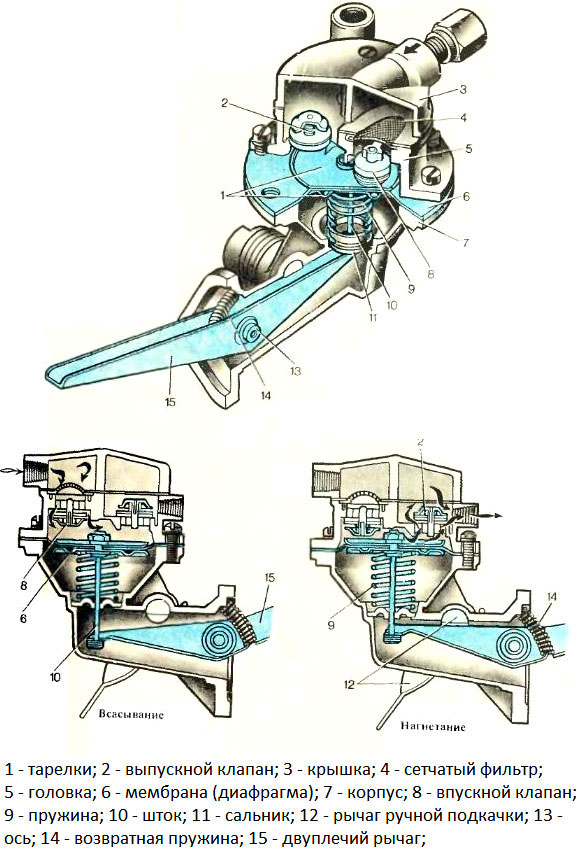
Diaphragm pumps are somewhat more complicated. The basis of the unit is a metal case with a round cavity, which is closed with a lid. Between the body and the lid there is an elastic diaphragm (diaphragm), connected by means of a rod to a lever or button on the pump cover. On the sides of the cavity there are inlet and outlet valves of one design or another (also, as a rule, ball).
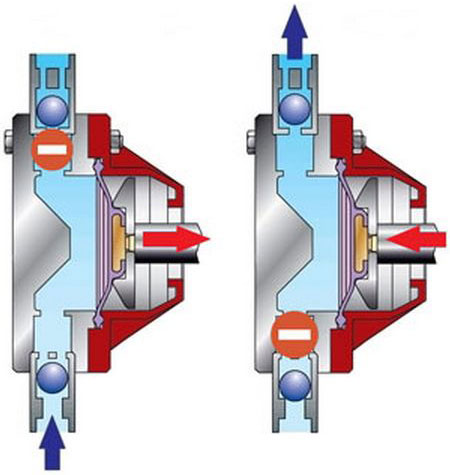
The operation of a diaphragm pump is similar to that of bellows units. Due to the force applied to the lever or button, the membrane rises and falls, increasing and decreasing the volume of the chamber. With an increase in volume, the pressure in the chamber becomes lower than atmospheric, which causes the intake valve to open - fuel enters the chamber. With a decrease in volume, the pressure in the chamber increases, the intake valve closes, and the exhaust valve opens - fuel enters the line. Then the process is repeated.

Working Principle of Diaphragm Pump
Diaphragm pumps are somewhat more complicated. The basis of the unit is a metal case with a round cavity, which is closed with a lid. Between the body and the lid there is an elastic diaphragm (diaphragm), connected by means of a rod to a lever or button on the pump cover. On the sides of the cavity there are inlet and outlet valves of one design or another (also, as a rule, ball).
The operation of a diaphragm pump is similar to that of bellows units. Due to the force applied to the lever or button, the membrane rises and falls, increasing and decreasing the volume of the chamber. With an increase in volume, the pressure in the chamber becomes lower than atmospheric, which causes the intake valve to open - fuel enters the chamber. With a decrease in volume, the pressure in the chamber increases, the intake valve closes, and the exhaust valve opens - fuel enters the line. Then the process is repeated.
Post time: Aug-21-2023
