In any piston internal combustion engine there is a part that connects the piston to the upper head of the connecting rod - the piston pin. Everything about piston pins, their design features and installation methods, as well as the correct selection and replacement of various types of pins is described in detail in the article.
What is a piston pin
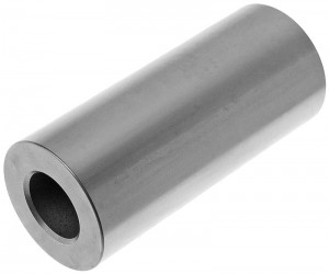
The piston pin (PP) is a component of the piston group of the internal combustion engine; steel hollow cylinder, with the help of which the piston and connecting rod are hinged.
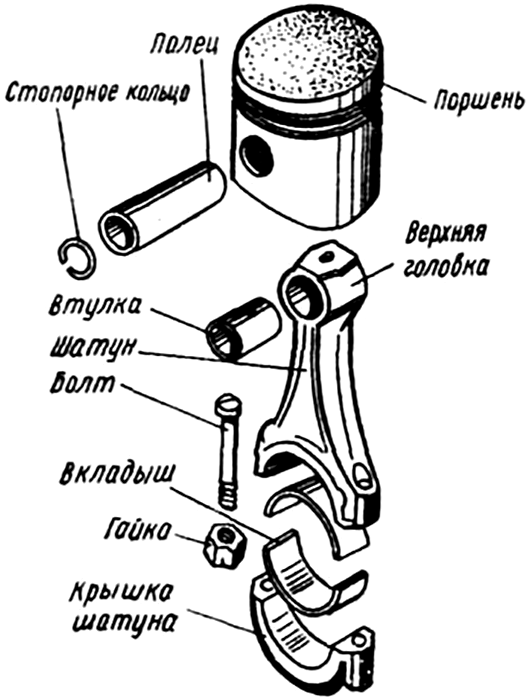
In reciprocating internal combustion engines, the transmission and conversion of forces arising from the combustion of the fuel-air mixture in the cylinder is carried out by a piston group and a crank mechanism. The main parts of these systems include a piston and a connecting rod with a hinge joint, due to which it is possible to deviate the connecting rod axis from the piston axis when it is between the upper and lower dead centers (TDC and TDC). The hinge connection of the piston and connecting rod is implemented using a simple part - a piston pin.
The piston pin solves two key tasks:
● Acts as a hinge between the piston and the connecting rod;
● Provides the transfer of forces and torques from the connecting rod to the piston when starting the engine and from the piston to the connecting rod when the engine is running.
That is, the PP not only connects the piston and connecting rod into a single system (which also includes the crankshaft), but also generally ensures the coordinated operation of the piston group and the engine crank mechanism. Therefore, any malfunctions or wear of the finger adversely affect the operation of the entire power unit, requiring speedy repair. But before buying new piston pins, you should understand their design and some features.
Types, device and characteristics of piston pins
All currently used piston pins have essentially the same design: in general, it is a hollow steel rod with relatively thin walls installed in the piston bosses and the upper connecting rod head. At the ends of the pin, chamfers (external and internal) are removed, which ensure easy installation of the part in the piston or connecting rod, and also prevent damage to other parts in case of accidental contact with them.
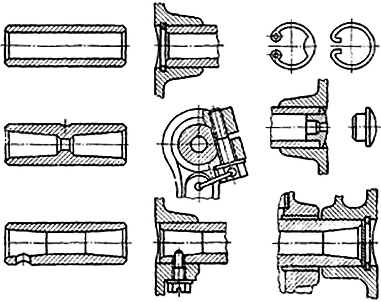
At the same time, various auxiliary elements can be performed in the fingers:
● Bringing the inner walls into a cone from the center to the outside in order to lighten the finger while maintaining its strength;
● Internal ring belts in the central part of the finger to harden it;
● Lateral transverse holes for rigid fixation of the pin in the piston boss.
Piston pins are made of soft structural carbon (15, 20, 45 and others) and some alloyed (usually chromium 20X, 40X, 45X, 20HNZA and others) steels. The outer surface and a small belt at the end of parts made of mild steels are carburized and quenched to a depth of 1.5 mm until a hardness of 55-62 HRC is reached (while the inner layer has a hardness in the range of 22-30 HRC). Parts made of medium carbon steels are usually hardened with high-frequency currents. After heat treatment, the outer surface of the PP is subjected to grinding. Hardening of the part provides high resistance of its outer surface to wear, while the viscosity of the inner layers of the wall retains the ability of the finger to withstand shock loads and vibrations. Surface grinding eliminates areas with dangerous stresses, which during engine operation can lead to scuffing, hardening or even destruction of parts.

Typical piston design with connecting rod
As already indicated, the piston pin is located in the piston and the upper head of the connecting rod, connecting these parts into one system. In the piston for this part there are two extensions with transverse holes - bosses. There are two design options for the hinge between the piston and the connecting rod:
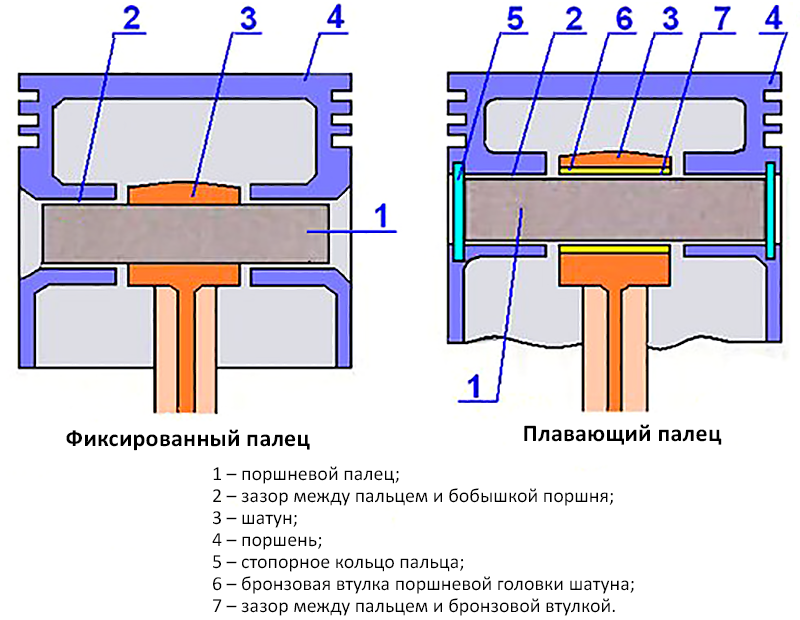
● With a "floating" finger;
● With a finger pressed into the connecting rod.
The second scheme is most simply implemented: in this case, the PP is pressed into the upper (one-piece) head of the connecting rod, which prevents its axial displacement, and in the bosses of the piston it is located with a certain gap, which makes it possible to turn the piston relative to the PP during the operation of the power unit in all modes. Also, the gap provides lubrication of rubbing parts (although due to the small gap, the finger and the surfaces of the bosses in contact with it always work in insufficient lubrication mode). This scheme was used on domestic cars VAZ-2101, 2105, 2108, it is widely used on modern models of foreign production.
The "floating" finger scheme is more complex, as it has several auxiliary parts. In this scheme, the PP with a small gap is installed in both parts - both in the piston bosses and in the upper connecting rod head, this ensures its free rotation during engine operation. To prevent axial displacement of the finger, springy retaining rings are used, located across the holes in the bosses - they serve as stops for the PP, preventing it from falling out. The rings can be made of spring wire with a circular cross-section or stamped from sheet metal. In the latter case, the parts have a rectangular cross-section, and holes for the tool are provided at both ends for ease of installation and removal of the rings.
In some cases, locking fungi or plugs are used, they are made of soft metal, so they do not damage the cylinder mirror when in contact with it. Plugs are used in two-stroke engines with a certain arrangement of intake and exhaust windows, preventing unwanted gas flow between them. Sometimes it is used to fix the part with a screw screwed into the lower part of the boss and into the hole at the end of the PP.

Fixed and floating piston pins
PP, regardless of the method of its installation, may have a displacement relative to the axis of the piston, reaching one and a half or more millimeters. This displacement is aimed at reducing the dynamic loads to which the piston, PP and connecting rod head are subjected during TDC and TDC. The piston in its movement to TDC and to TDC is pressed against one wall of the cylinder, which also leads to the pressing of the PP against one wall of the holes inside the bosses. As a result, there are forces that make it difficult to turn the PP in the mating parts, and when passing TDC and TDC, the turn can happen abruptly - this happens with a blow, which is manifested by a characteristic knock. These factors are precisely eliminated by installing PP in the piston with some axis displacement.
How to choose and replace the piston pin
During the operation of the engine, especially in alternating modes, the fingers are subjected to significant loads, they wear out, can be deformed and require replacement. The need to replace the fingers is indicated by the deterioration of compression and a decrease in the dynamic characteristics of the engine, which is additionally manifested by a characteristic knock.
Repair of the power unit in this case is reduced to the replacement of fingers, and sometimes mating parts - connecting rod head bushings in systems with "floating" PP, rings and others. The selection of new fingers and other parts is carried out according to the repair dimensions. For example, for most domestic engines, parts of three repair sizes are offered, differing by 0.004 mm (for example, VAZ engines often use pins with a diameter of 21.970-21.974 mm (1st category), 21.974-21.978 mm (2nd category) and 21.978-21.982 mm (3rd category)). This makes it possible to select pins of different diameters, taking into account the increase in the diameters of the holes in the mating parts due to wear and subsequent boring. Boring is always performed for the same repair dimensions, and if the wear of parts exceeds the specified ranges, then they must be replaced.
As a rule, fingers are sold in sets (2, 4 or more pieces), sometimes together with retaining rings and other parts.

Piston pins of various types and methods of their fixation in the piston
When repairing a piston group with "floating" pins, there is no need to use special equipment - the installation of parts in the bosses and connecting rod head is performed by hand effort. If the finger is changed with fixation in the connecting rod, then you have to use a special device for pressing and pressing the PP (in the simplest case, these can be bushings and rods, but professionals use more complex mechanized devices similar to a vice).
In some cases, the installation of the "floating" PP in the bosses is also carried out in interference, for this the piston is heated in water or other liquid to 55-70 ° C before installation. The fact is that an aluminum piston expands faster than a steel pin, so on an unheated engine, the gap between the parts increases and a knock appears. When installing the PP in the interference, the gap occurs only when the motor warms up, which prevents the impact of parts and, accordingly, knocking.
It should be noted that the work on replacing the piston pins requires significant disassembly of the engine, so it is better to perform them with appropriate experience or trust professionals. Only with the right selection of fingers and proper repair, the piston group will function reliably and efficiently, ensuring high performance of the power unit.
Post time: Jul-11-2023
